ITOS

The software package used in the MOC for the RHESSI mission is called ITOS (Integrated Test and Operations Software). It is a real-time control and monitoring system that receives/processes telemetry packets from the active ground station and handles commands. You can learn more about it here. The data is displayed in windows referred to as pages. Pages can be brought up by typing "page" in the ITOS command prompt, followed by the page name. The ITOS command prompt looks like so:

The following is a description of the pages important to the tohban:


igsespc: instrument ground support equipment spectrometer


IACCEL (Instrument Accelerometer) - attached to the cryostat. Measures the amount of vibration created by the mechanical cooler. Values should remain around 10-12 mG (milli-g's). Outliers are expected due to noise. Also, during transitions between stations (notably Berkeley-Wallops) bad telemetry packets are usually received, causing spurious values to appear. The button to the right of GND_IACCELAVG (labeled PI ) will make a time-series plot if desired.

ICRYOPWR (Instrument Cryostat Power) - measures power delivered to cooling in watts. Values should be around 53-54 W.

ISPCHTRTMR (Instrument Spectrometer Heater Timer) - shows in seconds how long the heater has been on. It is only turned on right before and after eclipse. While off, the value is zero.

ICP1T, ICP2T - cold plate temperature measured at 2 different parts of the cold plate. ICP1T is the part closer to the detectors, and thus we care more about this value, which should remain around 76 K.


buspower


This window displays information regarding the life/functionality of the power system of the spacecraft bus (i.e., of the battery, solar panels, and control electronics).

RH PRESS DIFF - measures pressure difference. Often this value is out of preset limits and is highlighted in red (as shown here) to indicate an abnormality. However, this is not a problem.


ssrcontrol: solid state controller


%FULL - Indicates the amount of memory currently being used. RHESSI keeps its data in a 4 GB buffer on board (in the Solid State Recorder [SSR]), operating as a large FIFO (First In, First Out), with a "read pointer" chasing a "write pointer" around and around. The data is downlinked at a rate of 4 megabits/s. A typical downlink reads slightly less than 5% of the SSR (~4.5%), and a typical day's observation fills about 50% of the buffer. Since RHESSI typically gets about ten contact passes per day, memory management is often a tricky business. If the value is below 20% then the thin shutter should be removed. Memory should be kept below 50% at all times so that it is available for major flares. Data decimation is turned on at 50%.

STORED SCIENCE PLAYBACK - usual mode of the pointer positions.

REAL TIME SCIENCE PLAYBACK - an option to move the read pointer next to the write pointer so one can read the recent times; use if you want to see most recent data.


monitor rates


Displays information on counts/sec received by each detector, both front and back segments. The front segment counts are usually high if the thin shutter is out. Rates in detector 8 can get high due to noise in transmitting the data from RHESSI's AFT antenna, so when receiving from AFT antenna, counts on GeD 8 are much higher than those for other detectors. It is possible to see which antenna is in use for receiving data by looking at SatTrack's "bar" window. Also note that detector 2 rear rates are null because it is operated at a voltage too low to divide it into segments -- all the counts end up in the front channel.

Particle background is displayed under "particle detector". Currently this display is backwards -- "Hi-E" is the lower-energy channel, which counts primarily electrons. There are often "storms" of electron precipitation over North America (i.e. during Berkeley and Wallops contacts). These can also cause rates (slow-valid and fast valid) to go very high. A solar flare pushes front rates much higher than the rears; electron precipitation makes the rear rates higher than the fronts. Trouble is when a single detector is very different from all the others (except for the two known anomalies above). In this circumstance, alert David Smith. The other particle detector channel counts protons (cosmic rays and SAA protons). It will seldom read more than "1" during contacts.

Monitor rates are averaged over 10 seconds, so the window updates only every 10 secs.

SLOW VALID - lower-level discriminator for analysis, slow because it's precise

FAST VALID - higher-level discriminator (higher energy threshold because it's fast)

SLOW > ULD - counts events too high in energy to analyze: i.e. cosmic rays.

Reset - counts the number of times per second that the electronics have to drain the capacitor in the preamp of each detector. If one gets very high, that detector has become leaky -- alert David Smith.

%Live Time - percentage time that the segment is *not* busy analyzing events. Generally over 90% except in the case of a very big flare or precipitation event.


acsmain: attitude control main page


Displays information on satellite pointing (SAS etc.).

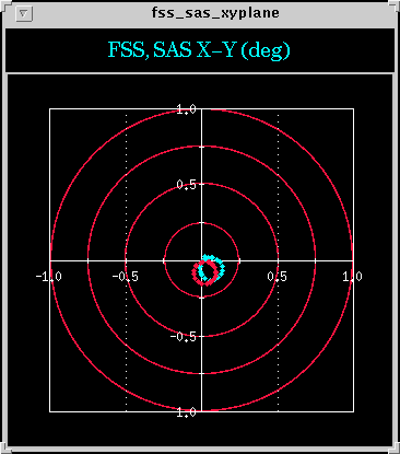
Fine Sun Sensor (FSS) Vector - X-Y button in the acsmain widget brings up a graphical display of FSS measurements. The SAS points are in red; the FSS points are in blue.


igseatten: attenuator (shutter) status


RHESSI has two shutters, one thick and one thin. Shutter 1 is thick and shutter 2 is thin. There are 4 possible shutter states displayed under IATTLEVEL:
0 - no shutters in
1 - thin shutter in
2 - thick shutter in
3 - both shutters in
The allowed states are displayed but only updated after GET button is pressed. State 2 is usually not allowed in order to minimise shutter movement, and the addition of the thin shutter may have little effect on the count rates when the thick shutter is already in.

IATTFLUX - displays a treshold derived from the deadtime of the detectors; triggers automatic shutter motions. When solar activity is low, value will be near 0%, which is too often the case. When a flare occurs, it begins to climb. If 8% is reached then the thin shutter automatically goes in. It will not remove itself until 5 minutes have passed and (?) the value has decreased to 3%. Note that when a change in shutter status causes spacecraft precession which can be noticed on the FSS display (see acsmain).


igseact: actuator status


ihv:


Displays the high voltages supplied to the GeDs. The first column lists raw counts; the second column lists conversions of the raw counts. Note that since GeD 2 is not functioning properly, its voltages are well below segmentation voltages. The high-voltage tohban is always David Smith.


igse_pages:


Gives a listing of some relevant instrument-related pages ("instrument ground-support equipment"), which are listed and described below.


igse_exec: executive


Displays data from flight software.


igseanlg: IDPU Voltages


Displays power supply voltages. IDPU stands for Instrument Data Processing Unit and handles all instrument activities.

IDPU Load Current - displays the power drawn by the collective IDPU. The value should remain ~1.9 Amps.

IDPUT - displays processor temperature, which should remain ~19.1 C.


igsescstat: spacecraft


Displays spacecraft state-of-health. All should be "ON" during contact.


igsehdr: tmheader


Displays telemetry header diagnostics.


igse_dib_pages: dib(s)


Each detector has its own data interface board (DIB). Pages for the 9 DIBS are listed in this widget.


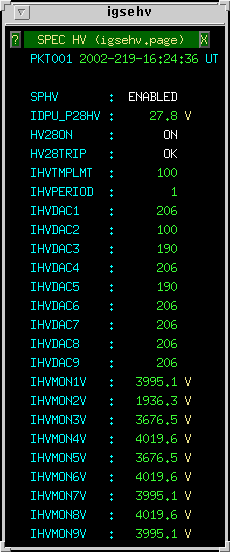
igsehv: spec hv


Displays the high voltages supplied to the GeDs. The first column lists raw counts; the second column lists conversions of the raw counts. Note that since GeD 2 is not functioning properly, its voltages are well below segmentation voltages. Lists essentially the same info as ihv.


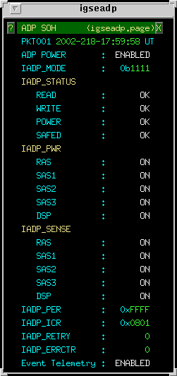
igseadp: ADP


Displays ADP state-of-health. All values should be "ON" or "OK".

IADP_PER - should be all F's.

IADP_ICR - value changes based on what controllers load.


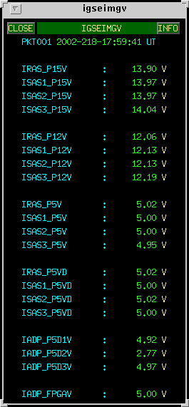
igseimgv: imager voltages


Displays voltages from various imager power supplies. Values should always be equal to or close to what they're rated as, that is, +/- 2V.


igseimgt: imager thermal


IUGTxT (instrument upper grid tray temperature) - should closely match the respective value for ILGTxT.

ILGTxT (instrument lower grid tray temperature) - should closely match the respective value for IUGTxT.

There should not be more than 2 degree difference between the temperatures of respective upper and lower grid trays. If the temperature discrepancy is larger, grid trays become misaligned and consequently, the signal getting through to the detectors becomes degraded.


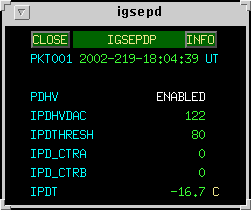
igsepd: particle detector


The particle detectors are primarily used for detecting the SAA, but they also propitiously detect particle storms occurring at high latitudes.

IPDHVDAC - digital-analog converter for high voltages.

IPD_CTRA - high energy particle counter, displays raw data. Displays the same information as does Hi-E in monitor_rates, except Hi-E displays a value averaged every 10 s, while this is a raw value.

IPD_CTRB - low energy particle counter, displays raw data. Displays the same information as does Lo-E in monitor_rates, except Lo-E displays a value averaged every 10 s, while this is a raw value.


igsedump: memory dump


Displays the 32 registers used for dumping data. Usually, only the first few registers are used, which is indicated by a change in their values. It is useful to compare the values before and after shutter changes have been made.


igsecom: communications


Displays information about communications between GeD electronics and instrument processor (IDPU).


igsepmt: PMT


Displays PMT information.

PMT HV (high voltage) - should be around 800 V.


igsesci: science


IAVGLIVE - combination of the livetimes of GeDs 3,4,5, and 6.


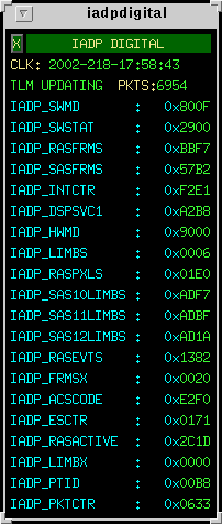
iadpdigital: ADP digitals


iadpstatus: ADP status


IADP_LIMBS - should display a count of 6 if the spacecraft is in daylight and pointed correctly.


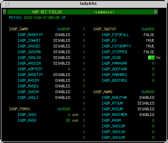
iadpbits: ADP bits


gnd_pass_params: pass parameters


tohban@ssl.berkeley.edu