University of California, Berkeley
Space Sciences Lab
7 Gauss Way
Berkeley, CA 94720-7450
cinema@ssl.berkeley.edu
Science Rules!
CINEMA System Overview
Consult the original National Science Foundation grant application for the full detailed report of the proposed science behind CINEMA.
Orbital Requirements
CINEMA is designed for a high inclination, low Earth orbit, such as the 72° inclination, 650 km altitude orbit planned for the first NSF Cubesat mission. Any such orbit (~500-800 km altitude) will allow measurements over nearly all geomagnetic latitudes. CINEMA could operate well in low Earth orbits at other inclinations without modification, while other orbits may require modifications.
STEIN (Suprathermal Electrons, Ions, and Neutrons) Sensor
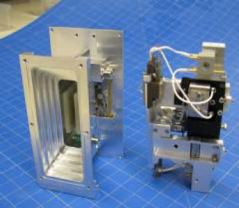
The STEIN (Suprathermal Electrons, Ions, & Neutrals) sensor for CINEMA adds a simple parallel plate electrostatic deflection system in front of the STEREO STE sensor to separate electrons from ions from neutrals.
Magnetometer
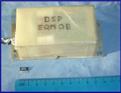
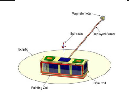
Anisotropic Magnetoresistive (MR) sensors are solid state devices that can measure the absolute value of the local magnetic field. CINEMA will have a MR MAG sensor at the end of the 1m extendable boom and an inboard MR MAG sensor, allowing operation in a gradiometer mode to identify and remove changes in spacecraftinduce fields, improve final calibrated data, and add redundancy.
CINEMA Spacecraft System Design
The CINEMA system consists of bus avionics which provides power, communications, and a Command and Data Handling System (C&DHS); plus two instruments; the magnetometer (MAG) and the STEIN electron/ion/neutral detector. The system is based on existing bus and instrument designs. Off-the-shelf cubesat avionics are used although if ITAR issues can be resolved these may be supplied by NASA Ames. The MAG electronics and sensors are provided by ICL based on existing Cubesat magnetometer designs. The remainder of the system is provided by UCB.
Power Systems
The Power system includes Triple Junction GaAs solar cells, Li-Ion batteries, battery charging and power conditioning/switching/monitoring circuitry (subsystem power switching is provided by the Instrument LVPS). There are a total of 10 1U-sized solar array panels spread over all 6 faces of CINEMA to provide power in any orientation). Each array consists of 2 large-format EMCORE cells in series.
Communications
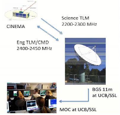
For commanding and engineering telemetry, the bus communications system includes a uHard 2.4 GHz WiFi transceiver (MHX2400), a 3-dB power splitter and two circular polarized patch antennas mounted on opposite sides of the spacecraft body. The combined antenna radiation pattern provides nearly omni-directional coverage. The receiver will always be turned on in SAFE mode, while the transmitter will be powered on in burst mode in response to commands received from the ground during a pass.
Mechanical
For commanding and engineering telemetry, the bus communications system includes a uHard 2.4 GHz WiFi transceiver (MHX2400), a 3-dB power splitter and two circular polarized patch antennas mounted on opposite sides of the spacecraft body. The combined antenna radiation pattern provides nearly omni-directional coverage. The receiver will always be turned on in SAFE mode, while the transmitter will be powered on in burst mode in response to commands received from the ground during a pass.
Attitude Control System
The ACS system consists of two torque coils, one v-slit Sun sensor, and the 3-axis science MAG. Additionally, solar array currents provide an extra coarse attitude sensor for initial attitude determination and the in-board calibration MAG is used for initial de-tumble activities. The ACS system is primarily used to take the spacecraft from its initial attitude and precess it to an ecliptic normal spinner. Once in that configuration, controls commands are required once per day to maintain the spin axis within a 10° cone, and the sensor data is sent to the ground for science attitude determination. The v-slit Sun sensor contains two collimated photodiode devices with 4° x 90° fan-shaped fields of view (FOV). This design has heritage from the UCB Rocket program. The devices are oriented looking in the spin plane, tilted 45° above and below, forming a V. Each device provides an event pulse whenever the FOV crosses the Sun. Therefore, the average of the pulse timing gives the Sun azimuth and the time between pulses gives the Sun elevation.
Related resources
- Original National Science Foundation Grant Application
- Karla Vega's thesis on Attitude Control Systems
Related Images

STEIN prototype

The Magnetometer, although sensitive and powerful, is only some 10 cm across

The schematic representation of internal satellite communication

Visual representation of the cubesat and its boom